|
The Art of Demomaking - Issue 02 - Introduction To Computer Graphics by (30 August 1999) |
Return to The Archives |
Introduction
 |
|
Welcome to the first proper tutorial in this series. This week I will start by introducing you to the very basics of computer graphics. As you will soon realise, all the principles you will learn can be applied in any context, from DirectDraw in Windows, to VESA under DOS, even for Linux. But to make things easier to understand, I will illustrate all these points using mode 13h, mainly because this is a very simple video mode. We may start using DirectDraw sometime in the future, but that's a while away :) After we've covered the most important aspects of modern graphics, we will create a simple Starfield effect with DJGPP. |
|
Setting The Video Mode
|
The first thing to do if you want to draw some stuff on the screen is to set the video mode you want to use. There are lots of different interfaces to video cards that help you do this, both high level (like DirectDraw) and low level (like VESA). Most of the time you only need to call a simple procedure:
As I mentioned in the introduction, we will use mode 13h. The interface we use is the lowest level possible: the BIOS. But mode 13h is still very easy to program, as you will quickly learn. The only thing you need to do to set the mode is call interrupt 10h with the value 13h in the register AX. You can think of a hardware interrupt as a call to the low level driver of a hardware component, in this case to the video card. Once the interrupt is over, you can assume mode 13h is set. There is very little need for error checking, since to my knowledge all video cards on PCs for the past 6 years have supported this mode. But if you were to set any other mode, especially under windows, I would strongly recommend checking that everything went according to plan :) Here's the part of the code that sets mode 13h:
|
|
Video Memory
|
|
Each video mode has it's resolution. Statistically, right now you're at resolution 1024x768 :) This means that there are 1024 picture elements (more commonly known as pixels) per line and 768 per column. Each pixel can be considered as a variable, like a byte (8 bit modes), a word (16 bit modes) or a double word (32 bit modes). In our case, mode 13h has a resolution of 320x200 with 8 bits per pixel. These are not high specs by today's standards, but they are fine for an introduction. And as I said earlier, you could later easily move to any other interface, since most of the concepts you will learn are also applicable. The major advantage with mode 13h is that the video memory is always at the physical address A0000h, which means it can be found at the same place on any PC. This is very useful since we can write pixels without worrying if they're actually there or not... Since we use DJGPP under protected mode, we just need to add the content of the variable __djgpp_conventional_base to A0000h and we get a valid pointer to the video memory. How you obtain this valid pointer is dependant on which interface you use, but once you have it, you can treat everything in the same way. You can now consider the video memory as a huge array. The first pixel is at index 0 of the array, and the rest of the first line goes on until index RESX-1. The next line starts at RESX, and goes on until RESX*2-1... Hence, index RESX*n is the start of the (n+1) th line. Note that in our case RESX = 320, but that could just as well be RESX = 1024. 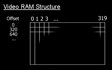 We can then easily draw a pixel at location (x,y) on the screen by using the following code:
You must setup video_buffer as an array of bytes in 8 bit modes, of words in 16 bit modes, and of dwords in 32 bit modes. |
|
Palettised Modes
|
In 8 bit modes, pixels can store 2^8 = 256 different values. Each of these 256 values are indexes that refer to a colour in the palette. The palette is therefore an array of 256 entries, for which each RGB components is specified. 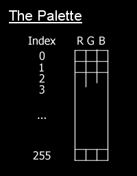 In mode 13h, these colour components are limited to the range [0..63]. The user can therefore select 256 colours from 262144 to store in his palette. The RGB values are simply uploaded to the graphics card through the port 3c9h. Just consider ports as a way to pass information to hardware devices. This is how we do it:
You can set the whole 256 colours by successively calling this procedure. |
|
High Colour and True Colour Modes
|
|
We won't be using high or true colour modes straight away, but I thought it would be best to explain them now. The main characteristic of both these types of video modes is that all the RGB information needed for one pixel is stored straight in the video RAM. High colour modes use 16 bits (sometimes only 15 bits) per pixel to store this information, using 5 bits for red, 6 (possibly 5) for green and 5 bits for blue. All this information is packed into a single word, so accessing each colour components separately is a bit tedious. 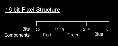 In True colour modes, you have 24 bits to store the RGB information, that's 8 bits per colour component. Accessing each colour component is therefore easier, since they occupy one byte each. Additionnally, some True colour modes use 32 bits per pixel... the extra 8 bits are sometimes used for alpha blending, but most importantly for padding. This means that the RGBA information occupies a whole DWORD rather than a WORD and a half. So accessing any pixel can be done with a left bit shift by 2 rather than a multiplication by 3, which is slightly slower. Don't worry if you didn't understand this last explanation, it's not really important yet, I just included it for completeness :) |
|
Choosing the Right Colour Depth
|
|
All these modes each have their own advantages, and obviously their disadvantages... 8 bit palettised modes Advantages: Disadvantages:
15/16 bits high colour modes Advantages: Disadvantages:
24/32 bit true colour modes Advantages: Disadvantages: Choosing the right video mode is a question of priorities, if you desperately need speed, then 8 bits per pixel is the obvious choice. For top quality, choose 32 bpp, and 16 bpp is a good compromise. |
|
Double Buffering
|
|
The screen is updated with the content of the video memory each refresh. How often depends on your monitor's and video card's refresh rate, but usually something like 60 times per second (that's 60hz). If we draw directly to the video memory, the screen may be refreshed while we are still drawing, so not all the information we wanted to be displayed is seen on the screen. The answer is to have a temporary buffer, in which all the drawing will take place. Once we have finished drawing in the temporary buffer, we can perform a block copy to video memory. There is a much smaller probability that the screen's retrace will happen while we are copying, since the copying is quite quick. But even so, this sometimes happens, and the screen is refreshed with a bit of the previous image, and a bit of the next image. This explains the ugly horizontal lines you get in some old demos that run too quickly. A simple solution is to wait for the monitor's vertical retrace. We are then sure that the whole frame will be refreshed. The following procedure waits for the screen's vertical retrace to finish, and then dumps the temporary buffer to the video memory.
Admittedly, it's a waste of time to wait for the screen every frame. If you use low level interfaces like the BIOS, there are some nifty techniques that save processing power by calculating the next frame while waiting for the retrace, but they're slightly too complex for the moment. But that's not much of a problem anymore since most modern APIs like DirectDraw and VBE 3.0 are capable of doing this for you. |
|
The Stars Example
|
|
The basic idea is that we represent each star as a pixel on the screen. Each star coordinate (x,y) must always lie within the screen. Hence when we move the stars, whatever the direction we must check that the coordinates are inside the screen. If they are outside, we randomly create a new star inside the screen. Even though this program's structure is very basic, most of the effects we will create also follow this pattern. First we perform all the initialisation, in our case setup the video mode, setup the palette and randomly generate the stars. Then we engage the main loop, which can either wait for a certain delay to run out, or for the user to press a key. All the drawing and real-time calculations are called from this main loop. In our stars example, every frame we must first clear the temporary buffer. Then we update and draw each star, and finally we can dump the temporary buffer to the screen. And start the loop all over again. Once the main loop is finished, we perform all the deinitialisation, in our case we must return to text mode and free the memory used by the stars. The code provided will show you how to do this. Download it here. (63 kb) |
|
Final words
|
You now have the basics to create simple effects based on the evolution of 2D points. It's up to you to learn more now... Modify the code, experiment, try some new ideas:
In the next tutorial, we will address a very important issue in both demomaking and game programming: Time Related Issues. We will also learn about fixed point math, basic linear interpolation, and implement a simple cross fader. Happy Coding, Alex |