 |

Submitted by , posted on 28 February 2002
|
 |
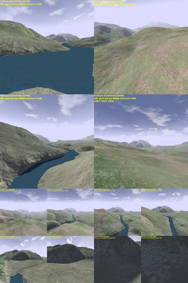
Image Description, by

Well, here it is - another terrain engine! I know there have been many lately,
but I think mine is a little different and somewhat interesting (and I'm proud
that I acually finished it!). The terrain you see was entirely generated with
Terragen and I found the world and heightmap files at an
online gallery. In retrospect, the simple hills and valley are a little plain
for a demo, but it took so long to create that I don't have the patience to do
it again!
The original intent of this demo was to create an engine that could display
hi-res satelite imagery and 3d terrain in realtime. I could then get data of
places I have been, and check them out from a different angle! Unfortunately,
the only high-enough-res data that I found costs thousands of dollars (anyone
know some sources?). I then fell back to using Terragen to create equivalently
high-res images. Since I wanted to use satelite imagery, there are no ecosystem
based effects. No detail textures. No artwork whatsoever. No flashy stuff.
Nothing. Its one texture for the terrain - as raw as it gets - and that's the
goal!
Actually, I lied. The entire scene is composed of two textures - the skybox and
the terrain map. The terrain map is a 16384x16384 RGB file (grand total of 268M
pixels!). In its uncompressed form, it consumes 768MB and after pre-computation,
it is over 1GB! The landscape is modelled to be 8192x8192 meters, giving the
terrain map a resolution of 4 pixels/m^2 - quite some detail! The terrain data
and texture data are stored in a quadtree-like data structure that facilitates
fast dynamic level-of-detail for both of them. In this demo, there are 128x128
bezier patches (sorry non-GeForce3+ users) that compose the terrain, and each is
associated with "relative" texture coordinates (uv's relative to the entire
terrain).
When rendering, the quadtree nodes are allocated/deallocated dynamically. For
each visible patch in a node, its actual area (in this case 8192/128=64m^2) is
divided by the projected screen space area and a resolution for the patch is
determined. Starting at the tree root, I traverse downwards until I find a
texture that covers the desired area and is at greater or equal resolution to
the patch. Patches don't contain texture coordinates in their vertex data (to
save memory) but a single vertex buffer with 16 texture coordinates (to match
the cubic patches' 4x4 vertices) in the range [0,1] are used along with a
texture matrix to compute the relative coordinates into the desired texture.
Some of you may be saying "hey, this is sort of like a super-mipmapping algo."
Yup, It is similar (although quite different in some respects) and it allows
keeping the pixel:texel ration between 1:1 and 1:2.
The bezier patches themselves also use a level-of-detail technique. Using the
screen space projected area, it is easy to determine how many segments are
needed to draw the patch at a certain resolution (pixels/segment). In my case, I
use 16 if it is relatively close and a geometrically precomputed lower-bound if
it is relatively distant. Since tesselating patches with different control
points would cause cracks in the terrain, each patch examines its neighbors
before rendering. It then tesselates its East edge according to the control
points of its East neighbor and does similarly with the South edge. Both North
and West edges are tesselated according to the patch's determined resolution,
regardless of neighboring patches.
You can see the result in the screenshots. The larger top-left and bottom-right
shots show you the landscape from 1.8 meters above ground, and the larger
bottom-left and top-right shots lift you by 100 meters or so. The 8 smaller
shots show a zoom sequence from 7 kilometers back to a closeup!
|
|